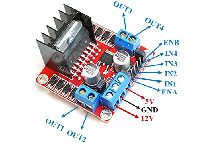

Acts as a 5V output if jumper is in place +5V: provide 5V if the jumper is removed.+12V: The +12V terminal is where you should connect your power supply.

To test this instruction, for example, you can utilise a bench power supply. In this lesson, four AA 1.5V batteries with a total output of around 6V will be used, but any other acceptable power supply can be used. It’s worth noting that, despite the +12V terminal’s designation, you may supply any voltage between 6V and 12V with the setup we’ll use here (with the jumper in place). If you want to supply more than 12V, remove the jumper and connect 5V to the +5V connector. When the jumper is in place, however, the chip is powered by the motor’s power source, so you don’t have to give 5V through the +5V terminal.

The L298N chip is powered by the +5V connector. The motors are powered by the +12V terminal block. OUT1 and OUT2 at the left and OUT3 and OUT4 at the right.Ī three-terminal block containing +12V, GND, and +5V is located at the bottom. The motor driver has a two-terminal block on each side for each motor. Let’s take a look at the L298N motor driver pinout and see how it works. Additionally, it allows us to drive two DC motors simultaneously, which is perfect to build a robot. We’re going to use the L298N motor driver that can handle up to 3A at 35V. The method we’ll use here is suitable for most hobbyist motors, that require 6V or 12V to operate. There are many ways to control a DC motor.

To complete this tutorial you need the following parts: Then we’ll teach you how to use the ESP32 with Arduino IDE and the L298N motor driver to control the speed and direction of a DC motor. We’ll start by looking at how the L298N motor driver works. The article demonstrates how to use an ESP32 and the L298N Motor Driver to control the direction and speed of a DC motor.


 0 kommentar(er)
